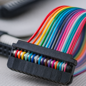
In electrical engineering and wire harness manufacturing, a signal is only as reliable as its end point. Wire termination is the process of treating the end of a wire to create a secure, high-quality connection to a device, switch, or another cable. Whether you are building a simple cable assembly or a complex automotive wire harness, proper termination prevents signal loss, heat buildup, and system failure.
I. Types of Wire Terminating and Joining
Wire termination is highly specialized based on the environment (indoor vs. outdoor) and the electrical requirements (voltage and current).
1. Passive vs. Active Termination
Passive Termination: Involves installing devices like resistors, transformers, or capacitors at the end of a line. This helps manage signal reflections without requiring an external power source.
Active Termination: Uses voltage regulators or active components to maintain a steady current voltage. This is common in high-speed data buses.
Forced Perfect Termination (FPT): A sophisticated form of active termination that locks signals between voltage regulators, widely used for single-ended buses to maximize performance.
2. Physical Joint Types
Straight-Through Joints: Simply connects two wires to extend the length.
Y and T Branch Joints: Used to split a single line into two directions. These joints are often waterproofed for outdoor use.
Pot End Joints: Safety caps used to terminate “abandoned” live-voltage cables, usually involving heat-shrink technology to seal the end.
II. Essential Wire Termination Methods
Choosing the right method depends on the production volume, mechanical strength required, and the materials being used.
Soldering: The wires are bonded using a filler metal (solder). This creates a highly durable, corrosion-resistant, and flexible connection.
Insulation Displacement Connection (IDC): A fast, low-cost method where the connector has sharp blades that pierce the wire insulation to make contact. No stripping is required.
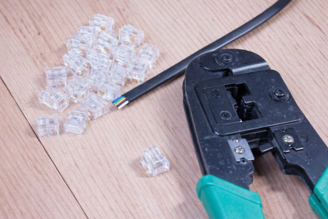
Crimping: The most common industrial method. A crimping tool applies pressure to a terminal to deform it around the wire, creating a “cold weld” that is mechanically strong and clean.
Ultrasonic Welding: Uses high-frequency vibrations to join metals like copper or aluminum without melting them. It creates a low-resistance metallurgical bond.
III. Key Applications and Impedance Standards
Different communication protocols require specific resistor values to prevent signal “bounce back” (reflection).
SCSI Units: Use active terminators with voltage regulators for data storage stability.
Controller Area Network (CAN): Standardized at 120 ohms to allow microcontrollers (like those in cars or elevators) to communicate.
Ethernet Cables: Typically require 50-ohm terminators for coaxial network jacks to prevent connectivity loss.
Antenna Networks: Standardized at 75 ohms for internet and television signals to avoid phasing problems.
MIL-STD-1553: A military standard for communication buses that uses specific resistors to ensure zero distortion in critical environments.
IV. Professional Installation Workflow
To ensure a connection lasts for years, follow this industry-standard five-step process:
Preparation: Cut the wire and strip the insulation (End Cut or Wire Strip). The surface must be free of dust, oil, and moisture.
Conductor Joining: Match the conductor to the correct connector. Note: Aluminum conductors require antioxidant paste to prevent the formation of insulating aluminum oxide.
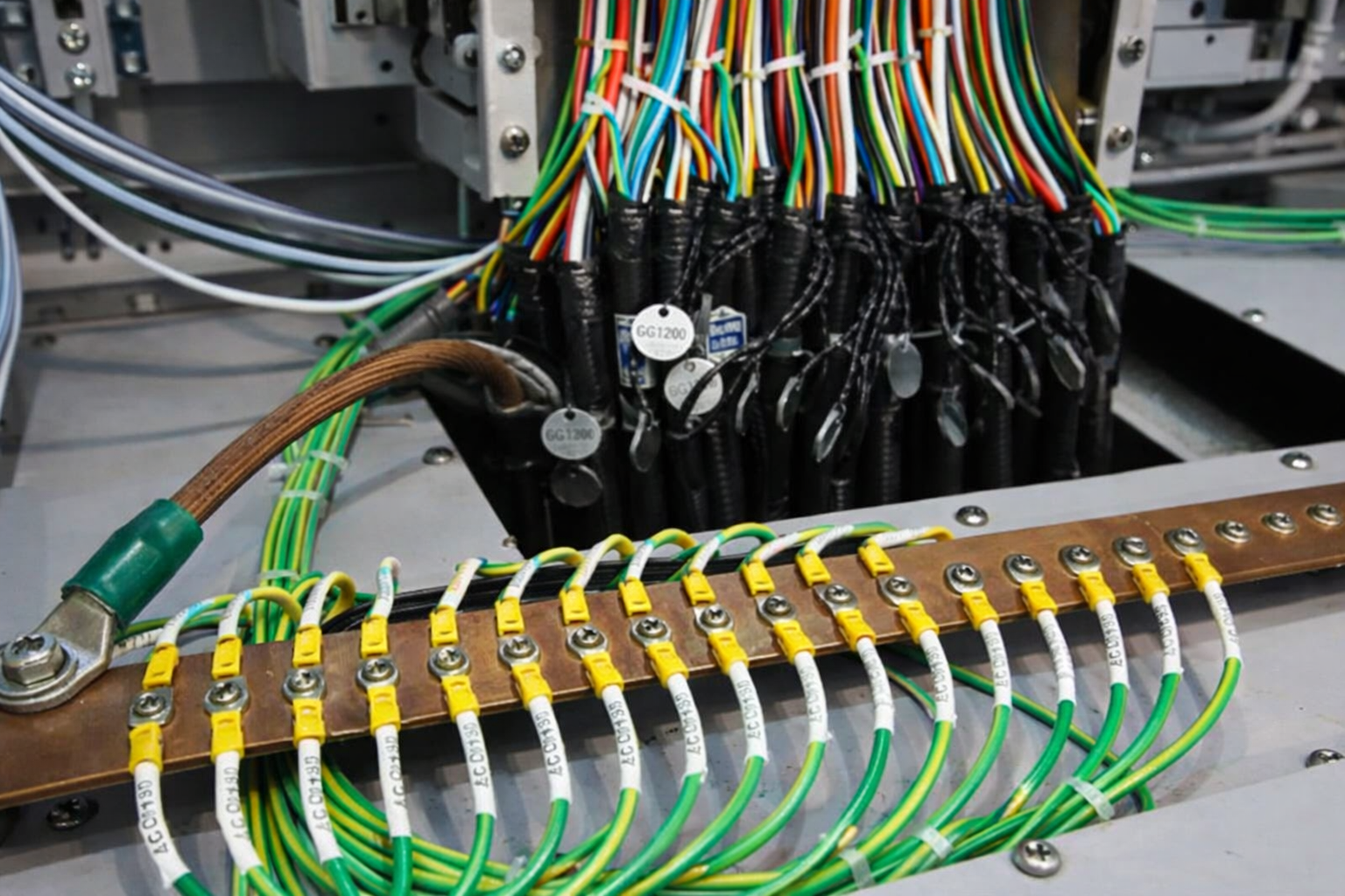
Insulation: Re-insulate the joint using electrical tape or, ideally, molded rubber splices to prevent air bubbles and moisture ingress.
Shield Replacement: If the cable is shielded, the metallic shield must be restored using specialized tapes to maintain EMI protection.
Jacket Recovery: The outer cable jacket is replaced using a combination of molded rubber and heat-shrink materials.
V. Wire Terminating Safety Protocols
Electrical work carries inherent risks. Always adhere to these safety fundamentals:
Personal Protective Equipment (PPE): Always wear protection boots and insulated gloves to guard against accidental discharges.
Zero Moisture Policy: Electricity and water are a lethal combination; ensure the environment is completely dry.
Tool Matching: Use the correct crimp die or solder tip for the specific wire gauge (AWG).
Monitoring: Use Online Partial Discharge (OPD) sensors to check the health of high-voltage cables and safety gear regularly.
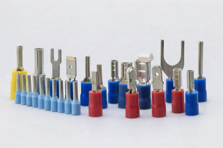
Technical Comparison: Ring, Spade, and Butt Connectors
| Terminal Type | Design Feature | Best Use Case | Primary Benefit |
| Ring Terminal | Circular “O” shaped loop. | Permanent connections to studs or bolts. | Security: Cannot be disconnected without completely removing the fastener. |
| Spade Terminal | Fork or “U” shaped opening. | Fast-paced assembly or frequent maintenance. | Convenience: Allows for quick connection/disconnection by simply loosening the screw. |
| Butt Connector | Cylindrical tube open at both ends. | Repairing broken wires or extending cable length. | Simplicity: Creates an in-line splice to join two separate wire ends together. |
1. Ring Terminals (The Secure Choice)
Ring terminals are the “gold standard” for safety. Because the bolt passes through the center of the ring, the wire cannot slip out even under extreme vibration.
Common Applications: Battery terminals, ground connections in vehicles, and heavy-duty industrial machinery.
Pro Tip: Use heat-shrink insulated ring terminals for outdoor or marine environments to prevent moisture from entering the crimp barrel.
2. Spade/Fork Terminals (The Flexible Choice)
Also known as “fork terminals,” these are designed for efficiency. You don’t need to take the screw all the way out; you just loosen it, slide the spade in, and tighten.
Common Applications: Terminal blocks, relay sockets, and speaker wire connections.
Pro Tip: Avoid using spade terminals in high-vibration environments (like near an engine), as they can eventually wiggle loose if the screw backs off slightly.
3. Butt Connectors (The Repair Choice)
When a wire is cut or needs to be longer, the butt connector acts as a bridge. You insert one wire in each end and crimp both sides.
Common Applications: Automotive wiring repair, extending harness lengths, and home DIY electrical fixes.
Pro Tip: For a professional, waterproof repair, use Solder Sleeve Butt Connectors. These contain a ring of low-temperature solder inside a heat-shrink tube that melts and seals the connection simultaneously with a heat gun.
Summary of Crimp Styles
Regardless of the terminal shape, the “crimp” itself must be performed correctly. A professional crimp should result in a “cold weld,” where the metal of the terminal and the wire strands are compressed so tightly that all air gaps are removed.
Would you like me to recommend a specific Crimp Tool (Manual vs. Hydraulic vs. Pneumatic) based on the wire gauge and production volume you are working with?
FAQs
1. Why is a specific resistance (like 120 ohms for CAN) required for termination?
In high-speed data lines, signals travel as waves. If the end of the wire is left open, the wave hits the end and reflects back down the wire, causing “noise” and data errors. The resistor absorbs the energy of the wave, simulating an infinitely long wire and preventing reflections.
2. When should I choose crimping over soldering?
Crimping is generally preferred in automotive and aerospace applications because it is faster for mass production and provides a consistent mechanical bond. Soldering is excellent for high-conductivity and permanent repairs but can make the wire brittle at the joint, leading to cracks under high-vibration conditions.
3. What happens if I use a copper connector on an aluminum wire?
This leads to galvanic corrosion. Because copper and aluminum are dissimilar metals, they react chemically when moisture is present, leading to high resistance and fire hazards. Always use AL/CU rated connectors or antioxidant pastes designed for this purpose.
4. What is the benefit of molded rubber splices over standard electrical tape?
Standard tape can unravel over time or allow air gaps (voids) to form. Voids are dangerous in high-voltage lines because they can cause “corona discharge” or internal arcing. Molded rubber splices provide a seamless, airtight, and flexible seal that is far more durable.
5. Can I use a 75-ohm resistor on a 50-ohm Ethernet system?
No. This is an impedance mismatch. Using the wrong impedance level causes significant signal loss and phasing problems, which can result in slow network speeds or total communication failure.
6. Is ultrasonic welding only for plastic?
While commonly used for plastics, Ultrasonic Metal Welding is a vital process for joining non-ferrous metals like copper and aluminum. It is highly valued in electric vehicle (EV) battery manufacturing because it doesn’t involve high heat, which protects sensitive nearby components.