Chapter 1: Understanding a Ribbon Cable
In the design of modern electronic devices, space conservation and efficient signal management are paramount. The use of a flat ribbon cable assembly addresses these basic needs, allowing for the discrete transmission of both power and data within compact internal compartments.
What is a Ribbon Cable?
A ribbon cable, also known as a multi-wire planar cable or hippie cable, is a type of cable that features many conductive wires running precisely parallel to one another on a single flat plane.
The flat, rectangular shape and inherent flexibility of the ribbon cable make it highly effective for simultaneous connection of multiple conductors and transmission of large volumes of data signals. A classic example illustrating its utility is its function in computer hardware, where it historically connected the disk drive to the disk drive controller via Parallel ATA (IDE) interfaces.
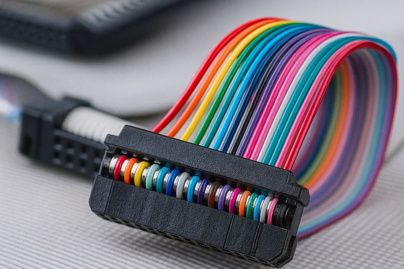
Ribbon Cable Color Coding
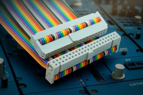
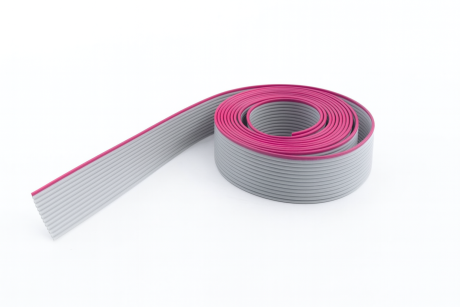
The purpose of color coding on a ribbon cable is critical: to prevent reverse connections which could damage the connected device. The universal rule dictates that the edge of the cable bearing a red stripe (or sometimes brown coloring) connects to pin 1 of the mating connector. This coding simplifies installation and aids in the easy identification of individual conductors within the assembly.
Ribbon Cable Size
Identifying the correct ribbon cable size involves considering two main factors:
The Pitch or Spacing of Conductors: This refers to the distance between the center of one conductor and the center of the next. The most common pitch is 0.05 inches (1.27 mm). This specific spacing allows the cable to mate with a two-row connector that has a standard pin spacing of 0.1 inches (2.54 mm).
The Number of Conductors (Ways): Ribbon cables are available in numerous standard conductor counts, such as 4, 6, 8, 10, 14, 20, 34, 40, 50, 64, and 80, dictated by the application’s requirements.
Benefits of Ribbon Cables
Space & Weight Efficiency: Their flat profile allows them to fit seamlessly into tight compartments and contribute minimally to the device’s overall weight.
Thermal Management: The ability to fold and organize the cables creates more open space within a chassis, enhancing airflow and reducing the risk of overheating.
Ease of Termination: They are highly compatible with Insulation-Displacement Contact (IDC) technology, allowing for fast, reliable mass termination using a simple hand press.
Electrical Quality: Ribbon cables possess excellent electrical qualities, ensuring they are good conductors capable of handling the required current capacity while maintaining signal integrity.
Simplified Troubleshooting: Their inherent organization eliminates the complexity associated with troubleshooting bulky, disorganized round wire bundles.
Chapter 2: Ribbon Cable Types
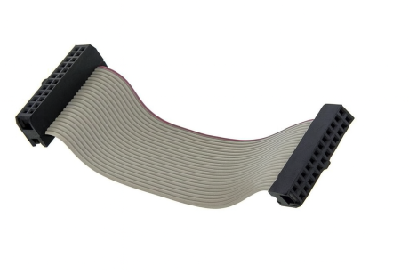
While the standard gray ribbon cable is the most recognizable, several specialized types exist to address specific electrical and mechanical requirements.
Rainbow Ribbon Cable: Functionally identical to the standard ribbon cable, but the individual wires are colored according to a repeating sequence (like the resistor color code). This provides enhanced visual clarity for wire organization and identification.
Twisted Flat Ribbon Cable: Unlike standard parallel cables, this type features adjacent conductor pairs that are twisted and bonded. The twisting significantly reduces electromagnetic interference (EMI) and crosstalk between adjacent signal lines, improving signal quality, especially at higher frequencies.
Standard Ribbon Cable: The most common type, typically gray, valued for its ease of mass termination using standard IDC connectors.
Round to Flat Ribbon Cable: This unique design features conductors that are grouped and often jacketed in a circular form at one end, which then transitions to a flat ribbon at the other. It combines the mass termination ability of ribbon cables with the routing flexibility often associated with discrete wire bundles, making it suitable for tight access areas.
Bonded Ribbon Cable: These cables have individual wires bonded together, resulting in an organized assembly that is less prone to becoming scattered. While less flexible than other types, they offer straightforward mass termination and excellent organization.
Folded Ribbon Cable Assembly: Designed specifically for extremely limited or dynamic spaces, these assemblies are pre-folded or creased to afford maximum installation flexibility, often requiring arrangement tools for permanent configuration.
Chapter 3: Ribbon Cable Connectors
The majority of ribbon cable connectors utilize IDC (Insulation-Displacement Contact) termination for fast assembly.
BT 224 Connector (IDC Connector): Defined by standards like DIN 41651 and MIL-C-83505. They mate with two-row header pins with standard 0.1-inch spacing and are commonly used with ATA cables.
D-Subminiature Connector: Although more common with crimp and solder terminations, IDC versions exist. They are typically used for serial ports (RS-232) and older printer ports (Parallel Port).
DIN 41612 Connector: Widely used across different suppliers and defined by the international standard IEC 60603-2. These are essential for bus architectures like Eurocard Bus and VMEbus, commonly featuring a female connector on a backplane mating with a male Eurocard bus on a daughterboard.
PCB Transition Headers: Connectors with dual rolls of pins that directly connect the ribbon cable to a Printed Circuit Board (PCB). They offer a cost-effective solution for permanent board-to-wire connections with long life and low contact resistance.
Micro Ribbon Connector (MDR): Also known as Mini-D Ribbon or Telco connector. Similar in shape to the D-Sub, its contacts are small metal bands (ribbons) rather than pins. They are secured by a bail lock and are crucial in telecommunication equipment and high-contact computer applications.
DIL Headers: Headers with pin spacing identical to standard Dual-In-Line (DIL) ICs. They are ideal for connecting two PCBs or replacing an IC to allow connection to an external device.
Chapter 4: Ribbon Cable vs. FFC (Flexible Flat Cable)
While often confused, the terms Ribbon Cable and Flexible Flat Cable (FFC) describe distinct products with different construction methods and performance characteristics.
Flexible Flat Cable (FFC)
FFC is a highly specialized type of ribbon cable that consists of multiple conductors laminated between a thin, flat, flexible plastic film base (often polyester). FFCs are defined by their extreme flexibility, allowing them to bend and fold within high-density, dynamic electronics.
FFC vs. FPC (Flexible Printed Circuit)
FFC (Cable): A simple cable where conductors (usually flat copper strips) run parallel on a flexible plastic film.
FPC (Circuit Board): A much more complex product. It is a true flexible circuit board where a conductive circuit is chemically etched and sandwiched between elastic polymers. FPC is thinner, lighter, and functions as a flexible substrate for mounting components, making it more than just a simple cable.
Key Differences: Ribbon Cable vs. FFC
| Feature | Standard Ribbon Cable | Flexible Flat Cable (FFC) |
| Flexibility | Good, but conductors can shift within the jacket during motion. | Superior; conductors are isolated and stable. |
| Construction | Separate round wires bonded or jacketed together. | Conductors are flat, laminated foil strips. |
| Signal Quality | Prone to minor wire coupling/crosstalk issues. | Better Signal Integrity; offers sophisticated EMI/RFI suppression. |
| Efficiency | Good for packaging volume. | Superior in heat, weight, and volume efficiency. |
| Termination | Uses IDC (piercing). | Uses ZIF/LIF (Zero/Low Insertion Force) connectors. |
In summary, FFCs are generally considered to possess superior features for high-performance, dynamic applications due to better thermal, weight, and signal management.
Chapter 5: How to Choose Ribbon Cable
Selecting the correct ribbon cable requires balancing electrical needs with mechanical constraints.
Pitch (Spacing): Match the ribbon cable pitch to the connector requirement. The standard pitch is 0.05 mm. If using a 0.1-inch (2.54 mm) two-row connector, the cable pitch is typically half the connector pin spacing (0.05inch).
Flexibility and Motion: If the application requires repeated, dynamic motion, a Twisted Flat Ribbon Cable (for signal integrity) or a high-strand-count FFC (for mechanical resilience) is necessary. For harsh temperatures or severe flexing, choose a custom cable with a durable silicone jacket.
Longevity and Reliability: Always prioritize products that are professionally proven and assured of a long life cycle, especially in critical applications like military or aerospace.
Fire Resistance & Compliance: Ensure the cable type complies with the EU’s Restriction of Hazardous Substances (RoHS) Directives and meets relevant fire safety standards for both equipment protection and operator safety. Contact us for more information.
FAQs
1. What is the main benefit of a Ribbon Cable compared to a standard Round Cable?
The main benefit is space efficiency and organization. Because the conductors are laid flat and parallel, ribbon cables can fit into tight spaces where bulky round cables cannot. Additionally, their inherent flatness eliminates the need for extensive cable management, simplifying assembly and troubleshooting.
2. Why is the red stripe on a ribbon cable so important?
The red stripe (or sometimes blue or brown) denotes the orientation of the cable, specifically marking the wire that connects to Pin 1 of the connector. This is crucial for maintaining the correct signal path and preventing a reverse connection which could damage sensitive electronic components in the connected device (e.g., a disk drive controller).
3. What is the difference in termination method between a standard Ribbon Cable and an FFC?
Ribbon Cables typically use Insulation-Displacement Contact (IDC) connectors. This method relies on sharp blades penetrating the insulation to establish contact with the conductor, allowing for fast, mass termination without prior wire stripping.
FFC (Flexible Flat Cables) use ZIF (Zero Insertion Force) or LIF (Low Insertion Force) connectors. The FFC slides into the connector, and a lever or slider locks the cable in place, relying on the cable’s pre-exposed, plated contacts.
4. Why are Twisted Flat Ribbon Cables used, and what problem do they solve?
Twisted Flat Ribbon Cables are specialized cables where conductor pairs are twisted together before being bonded into a flat profile. They are used to reduce crosstalk (signal interference between adjacent wires) and improve noise immunity (EMI/RFI suppression), making them ideal for transmitting high-speed or sensitive data signals over longer distances compared to standard parallel ribbon cables.
For the most common type of connection (a two-row connector), the ribbon cable pitch is typically half of the connector’s pin spacing.
Example: If the connector has a pin spacing of 0.1 inch (2.54 mm), the standard ribbon cable pitch will be 0.05 inch (1.27 mm) to ensure the cable contacts align correctly with both rows of pins.
6. What is the fundamental difference between FFC (Flexible Flat Cable) and FPC (Flexible Printed Circuit)?
FFC is a cable—a collection of parallel conductors laminated onto a flexible film, used primarily for connecting two components.
FPC is a circuit board—a flexible substrate with an etched circuit pattern, capable of supporting mounted electronic components (like resistors or ICs). FPC is more complex and typically used to replace rigid PCBs in space-constrained or flexing applications.
7. In what applications is an FFC preferred over a standard Ribbon Cable?
FFC is preferred in applications that require high cycle life (repeated bending) and extreme space efficiency. This includes modern consumer electronics such as:
Printers (connecting the print head to the main board)
Scanners and copiers
Laptops and mobile phones (connecting display hinges or camera modules)
FFC’s lamination process ensures the conductors do not move, maintaining electrical properties during flexing.