Introduction: The Integrity of the Circuit
The fundamental concept underpinning any electrical or electronic device is the closed circuit—a continuous, circular path that permits the flow of electrical current from a power source, through a load, and back to the source. The operational integrity of this path is defined by continuity. If this pathway is broken or obstructed, continuity is lost, and the device fails to function.
A continuity test is the most basic, yet crucial, diagnostic step in electronics. It verifies that a circuit segment offers a negligible barrier to current flow. Understanding not just what continuity is, but how to measure and interpret its findings across various components, is essential for any technician or hobbyist.
What is a Continuity Test?

What is a Continuity Test
Definition and Technical Basis
A continuity test is a quick measurement performed to determine if there is an unbroken electrical path between two points. Technically, the test measures the electrical resistance in ohms ($\Omega$).
Perfect Continuity: Indicated by $0 \Omega$. This is an ideal, theoretical connection with no impedance.
Good Continuity: Indicated by resistance near zero (typically $< 5 \Omega$). A continuous, functional path exists.
Lack of Continuity (Open Circuit): Indicated by infinite resistance, often displayed as “OL” (Over Limit) or “1” on a digital meter. This means the path is broken.
The test provides a small voltage from the testing device to determine if current can flow. Interruptions can result from damaged conductors, cracked wires, cold solder joints, or failed components.
Tools for the Test
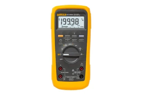
Digital Multimeter (DMM): The most common tool, offering quantitative resistance readings.
Ohmmeter: A device dedicated solely to measuring electrical resistance.
Specialized Continuity Tester: A basic, low-cost tool that provides only a qualitative (Go/No-Go) indication, usually with a light or buzzer.
Why Conduct a Continuity Test? (Applications)
Continuity testing is the first line of defense in diagnosing electrical malfunctions, helping to pinpoint issues that are often invisible to the naked eye.
Verifying Solder Quality: Detects cold solder connections—joints that appear connected but have high resistance or are completely separated due to poor metallurgical bonding.
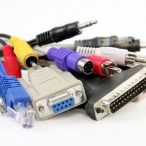
Locating Broken Conductors: Identifies internal breaks in power cords, extension cables, or headphone wires that may look perfectly normal externally.
Component Isolation: Used to quickly determine if certain passive components (like fuses or inductors) have failed in an open state.
PCB Tracing: Essential for debugging Printed Circuit Boards (PCBs) to verify that two designated points are connected (or not connected) by a trace, thereby verifying the board’s layout against the schematic.
Schematic Validation: Confirms that the physical wiring of a prototype or repair matches the intended electrical path defined in the schematic diagram.
How to Test Continuity with a Multimeter
How to Test Continuity with a Multimeter
The most effective method utilizes a Digital Multimeter (DMM), which offers high precision and a clear audio indicator for continuity.
Multimeter Setup and Safety
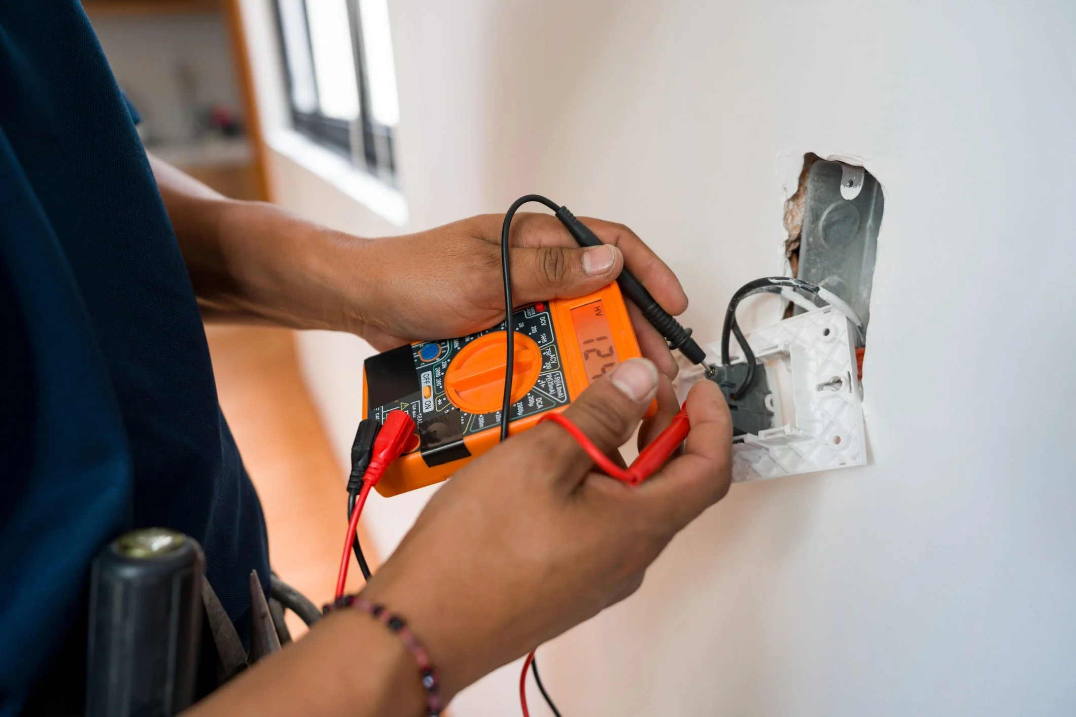
Power Down: Crucially, always turn off and unplug the device or circuit under test. Continuity testing must never be performed on a live circuit, as this can damage the meter and pose a safety hazard.
Leads: Plug the black probe into the “COM” (Common) port and the red probe into the “mAVΩ” (Amperage, Voltage, Ohms) port.
Mode: Set the function dial to the Continuity Mode. This is typically indicated by an audible wave symbol or a diode symbol with sound waves. The meter will emit a beep when resistance is sufficiently low.
Calibration Check: Touch the metal tips of the red and black probes together. The meter should immediately beep and display $0.0-0.5 \Omega$. If it shows “OL” or no beep, the meter’s leads or battery may be faulty.
A. Continuity Test for Capacitor (De-energized & Removed)
Before testing, the capacitor must be removed from the circuit and completely discharged to prevent erroneous readings.
| Test Mode | Expected Reading (Good Cap) | Interpretation | Damaged State |
| Continuity Mode | Starts near $0 \Omega$, then slowly climbs to “OL” | The multimeter’s internal battery charges the capacitor. Once fully charged, the capacitor acts as an open circuit. | Short: Reading remains near $0 \Omega$. Open: Immediately shows “OL.” |
| Resistance Mode | Starts near $0 \Omega$, climbs to $\infty$ | Confirms the charging cycle. The final reading represents the leakage resistance. | Short: Low resistance. Open: Immediate high resistance. |
B. Continuity Test for Inductors (Removed from Circuit)
An inductor is essentially a coil of wire.
| Test Mode | Expected Reading (Good Inductor) | Interpretation | Damaged State |
| Continuity Mode | Beeps; displays a very low value ($< 1 \Omega$) | Confirms the physical integrity of the wire coil. | Open: Shows “OL” or “1.” |
| Resistance Mode | Displays the DC Resistance (DCR), a few ohms | Confirms the inductor is not open. The DCR depends on the wire length and gauge. | Open: Displays $\infty$. Short Turns: Displays resistance significantly lower than the specified DCR. |
C. Continuity Test for a Wire or Cable (De-energized)
This test confirms that the conductor is sound from end to end.
Place the black probe firmly on the exposed metal of one end of the wire.
Place the red probe firmly on the exposed metal of the opposite end of the wire.
Interpretation of Readings:
$0.0 \Omega$: Perfect continuity (ideal).
$0.1 \Omega – 1.0 \Omega$: Excellent continuity (expected for short cables).
$1 \Omega – 10 \Omega$: Acceptable only for very long wires or specialized loads; otherwise indicates poor continuity or high resistance.
“OL” or “1”: Broken circuit (the wire is cut internally).
D. Continuity Test for Fuse
A fuse is a simple link. Its purpose is to have $0 \Omega$ continuity when functional.
| Fuse Condition | Multimeter Reading | Interpretation |
| Good Fuse | Zero ($0 \Omega$) or nearly zero | The internal metal strip is intact. |
| Blown Fuse | Infinite (“OL” or “1”) | The internal metal strip has melted, creating an open circuit. |
E. Continuity Test for Switch/Push Buttons
Switches must be tested in both their open and closed states to confirm proper operation.
Connect the probes to the terminals of the switch.
Test 1 (Switch ON/Closed): Press or toggle the switch to the ON/Closed position. The meter must read $0 \Omega$ (continuity).
Test 2 (Switch OFF/Open): Release or toggle the switch to the OFF/Open position. The meter must read $\infty$ or “OL” (open circuit).
Failure Modes:
Stuck Closed (Short): Reads $0 \Omega$ in both positions.
Stuck Open (Open): Reads $\infty$ or “OL” in both positions.
How to Test Continuity without A Multimeter
While a multimeter provides quantitative data, a simple qualitative tester can confirm if a path exists.
A. Dedicated Continuity Tester
A specialized tester typically consists of an internal battery, an indicator (LED, bulb, or buzzer), and two leads (one probe, one alligator clip).
Working Principle: The device forms a simple series circuit with the component under test. If the component provides a continuous path, the circuit completes, and the low current from the battery activates the indicator.
Safety: Always ensure the circuit or device being tested is de-energized.
B. Homemade Continuity Tester
For emergencies, a simple tester can be constructed:
Components: A 9V battery, a low-current indicator (like an LED with a current-limiting resistor, or a small buzzer), and two connecting wires.
Assembly: Connect the battery, indicator, and one test wire in series. The second test wire connects from the indicator back to the battery terminal.
Testing: The two free ends of the test wires are applied to the points of the circuit being checked. If the light or buzzer activates, continuity exists.
Conclusion
Continuity testing is the cornerstone of electrical troubleshooting, providing immediate and critical insights into the physical integrity of a circuit. Whether you are validating a PCB trace, diagnosing a faulty power cord, or confirming the state of a switch, the technique is invaluable. Mastering the use of a multimeter—understanding the meaning of $0 \Omega$, low $\Omega$, and “OL”—allows you to quickly pinpoint faults and determine necessary repairs. To preemptively minimize continuity issues, prioritizing high-quality cable assemblies and wiring harnesses is always the best practice.