Installing an aftermarket stereo can be intimidating, especially for first-time installers. Modern vehicles contain complex electrical systems, and a single incorrect wire connection can lead to malfunctioning equipment, blown fuses, or a drained battery. Among the most misunderstood connections is the blue and white wire on radio harnesses.
Many installers ask: What does the blue and white wire do? Where should it be connected? What happens if it’s wired incorrectly? This article provides a comprehensive, step-by-step technical explanation of stereo harnesses, installation methods, and—most importantly—the correct function and wiring of the blue and white wire.
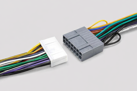
What’s a Stereo Harness?
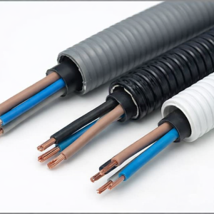
A stereo wiring harness is an adapter designed to connect an aftermarket head unit to a vehicle’s factory wiring system without cutting or modifying the original wires. It acts as an interface between the vehicle and the new stereo, ensuring proper power delivery, speaker connections, and accessory control.
Stereo harnesses serve several key purposes:
Maintain factory wiring integrity
Simplify installation
Reduce wiring errors
Allow easy stereo removal or upgrades
There are also specialized harnesses available, including:
Amplifier bypass harnesses for vehicles with factory amps
Extension harnesses for relocating head units
Integration harnesses that retain steering wheel controls or factory features
Choosing the correct harness for your specific vehicle and head unit is critical to avoid compatibility issues.
How to Install an Aftermarket Stereo
There are two main installation methods: using a harness adapter or wiring without a harness.
Installing an Aftermarket Stereo Using a Harness
This is the preferred and safest method.
Select the Correct Harness Adapter
Harness adapters are vehicle-specific. You must match:
Vehicle make
Vehicle model
Model year
Head unit brand
Confirm Compatibility
Even when a harness is available, not all features may be supported. Always verify amplifier integration, antenna type, and accessory power compatibility.
Use Wiring Diagrams
Most aftermarket head units include a wiring diagram printed on the chassis or in the manual. Harness adapters usually follow standardized color coding, reducing guesswork.
Match and Connect Wires
Match the vehicle harness colors to the head unit harness colors, then connect them using solder, crimp connectors, or pre-terminated plugs.
Plug and Test
One end of the harness plugs into the factory connector, and the other plugs into the head unit. Test all functions before final mounting.
Installing an Aftermarket Stereo Without a Harness
In some cases, a compatible harness adapter may not exist—particularly for older vehicles, imported models, or custom installations.
When installing without a harness:
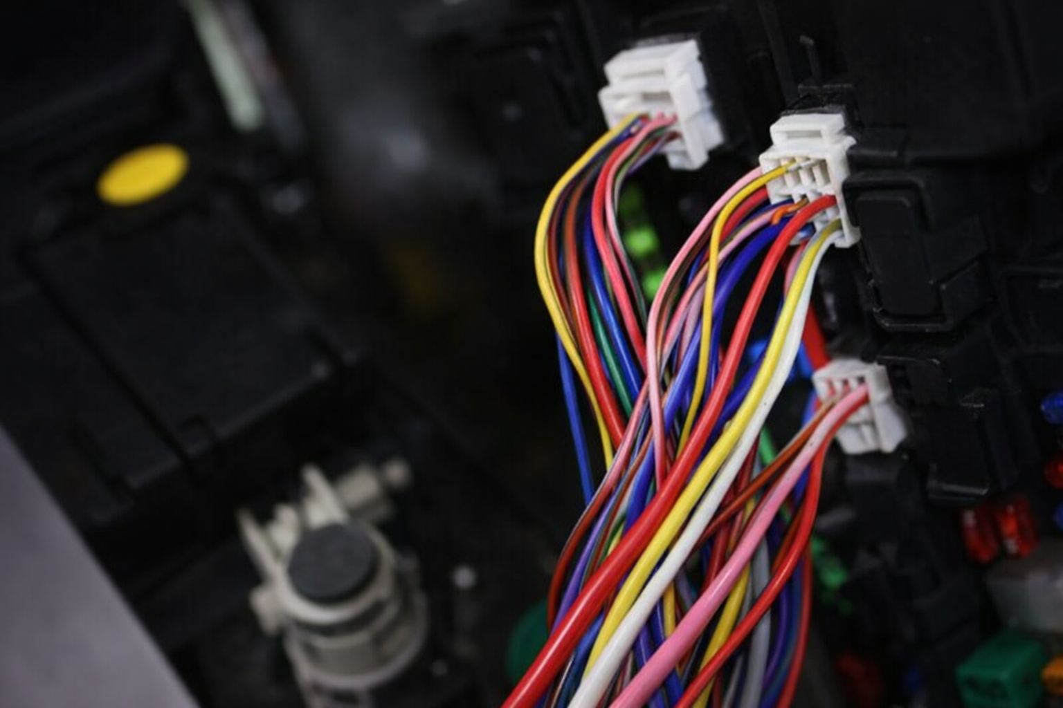
You must manually identify vehicle wires using wiring diagrams or a multimeter
A pigtail connector from the head unit is used to connect individual wires
Direct pin-to-pin wiring may be required
This method increases installation complexity and risk. Incorrect connections can damage the head unit or vehicle electronics, so careful planning and wire identification are essential.
Benefits of Using a Head Unit Harness Adapter
Using a harness adapter offers several advantages:
Faster installation time
Reduced chance of wiring errors
No permanent vehicle wiring modification
Easier troubleshooting and future upgrades
Professional-grade installation finish
For most users, a harness adapter is the most reliable solution.
Why Choose Splicing Wires over Using Harness Adapters?
Wire splicing becomes necessary when:
No compatible harness exists
Custom audio systems are installed
Multiple amplifiers or accessories are added
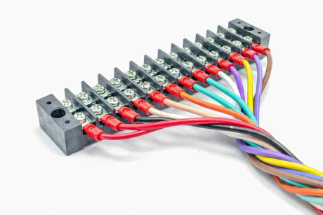
Splicing allows flexibility but requires technical skill. Each wire must be correctly identified, securely connected, and insulated to prevent electrical faults.
Understanding the Blue and White Wire on Radio Harnesses
Function of the Blue and White Wire
The blue and white wire is commonly known as the amplifier remote turn-on wire. Its purpose is to control when an external amplifier turns on and off.
It receives a low-current 12V signal from the head unit
Voltage is present only when the ignition is in the ON or ACC position
When voltage is detected, the amplifier powers on
When voltage stops, the amplifier shuts off
This prevents the amplifier from running continuously and draining the battery.
The blue and white wire may also be referred to as:
Remote wire
Amp turn-on wire
Accessory control wire
Blue and White Wire vs. Solid Blue Wire
Many installers confuse these two wires, which can cause system failures.
Blue/White Wire: Amplifier remote turn-on
Solid Blue Wire: Power antenna or factory amplifier trigger
They serve different functions and should not be interchanged unless specified by the vehicle manufacturer.
Wiring the Blue and White Wire on Radio Harnesses
Standard Aftermarket Head Unit Wire Color Codes
Most aftermarket stereos follow a standardized color system:
| Wire Color | Function |
| Red | Accessory / Switched 12V |
| Yellow | Constant 12V / Memory |
| Black | Ground |
| Blue/White | Amplifier Remote |
| Blue | Power Antenna |
| Orange | Illumination |
| White / White-Black | Front Left Speaker (+ / -) |
| Gray / Gray-Black | Front Right Speaker (+ / -) |
| Green / Green-Black | Rear Left Speaker (+ / -) |
| Purple / Purple-Black | Rear Right Speaker (+ / -) |
This standardization greatly simplifies wiring across different head unit brands.
Connecting the Blue and White Wire
Identify the blue/white wire on the head unit harness
Connect it to the corresponding blue/white wire in the vehicle or harness adapter
Route the wire to the amplifier’s remote terminal
Secure the connection using a reliable splicing method
Splicing Methods for Blue and White Wire Connections
Soldering (Recommended)
Strongest and most reliable method
Requires proper insulation using heat shrink tubing
Ideal for long-term installations
Heat Shrink Tubing
Protects against moisture, vibration, and corrosion
Used in combination with solder or crimp connectors
Butt Connectors and T-Taps
Faster installation
Must be correctly sized and crimped
Less durable than soldering
Scotch Locks
Quick but less reliable
Suitable only for low-current signal wires
Not recommended for permanent installations
Things Not to Do When Wiring the Blue and White Wire
Do Not Jumper Constant Power to the Remote Turn-On
Connecting the amplifier remote wire directly to constant power will:
Keep the amplifier permanently on
Drain the vehicle battery
Cause overheating and premature amplifier failure
Always ensure the blue/white wire only receives power when the ignition is on.
Do Not Connect Blue and White Wire to the Power Antenna in Modern Vehicles
In older vehicles, the power antenna activated whenever the radio turned on. In modern vehicles:
The antenna only receives power in FM/AM mode
Switching to AUX, Bluetooth, or satellite radio cuts power
This causes the amplifier to shut off unexpectedly
Always connect the blue/white wire to the correct remote output on the head unit.
Conclusion
Understanding stereo harnesses and wire functions is essential for a successful aftermarket stereo installation. The blue and white wire plays a critical role in controlling external amplifiers and protecting your vehicle’s electrical system.
By using proper harness adapters, following standardized color codes, and avoiding common wiring mistakes, you can achieve a clean, reliable, and professional installation. When in doubt, consult wiring diagrams or seek expert assistance to prevent costly errors. Contact us for more information.
FAQs
1. Why does my amplifier not turn on even though the blue and white wire is connected?
This is one of the most common issues and usually results from one of the following causes:
No 12V output from the head unit’s blue/white wire
Loose, poorly crimped, or broken splice
Incorrect ground connection on the amplifier
Blown fuse on the amplifier or inline fuse holder
Troubleshooting steps:
Use a multimeter to check for ~12V at the blue/white wire when the head unit is ON.
If there is no voltage, verify the head unit settings—some stereos require enabling the amplifier remote output in the menu.
Check continuity between the head unit and amplifier remote terminal.
Confirm the amplifier ground is clean, tight, and connected to bare metal.
2. The amplifier turns on, but turns off randomly while driving. What causes this?
Intermittent amplifier shutdown is often caused by an unstable remote signal.
Common reasons include:
Blue/white wire connected to the power antenna wire instead of the remote output
Poor splice that loses contact due to vibration
Remote wire routed near high-current power cables causing electrical noise
Best practice:
Ensure the blue/white wire is connected directly to the head unit’s remote output and secured using solder or high-quality crimp connectors.
3. My amplifier stays on even when the ignition is off. What went wrong?
This usually means the blue and white wire is connected to a constant 12V source instead of a switched or remote output.
Possible incorrect connections:
Yellow (constant power) wire
Battery positive terminal
Fuse box terminal with continuous voltage
Fix:
Reconnect the blue/white wire to the correct remote turn-on output from the head unit or an ignition-switched accessory source.
4. Can I use one blue and white wire to turn on multiple amplifiers?
Yes, this is a common and acceptable practice.
However, keep the following in mind:
The head unit remote output is low-current (typically 200–500 mA max)
Too many amplifiers or accessories may overload the circuit
Professional solution:
Use a relay if you are triggering multiple amplifiers, DSPs, or powered accessories. The blue/white wire should trigger the relay, and the relay should distribute power to all devices.
5. Why do I hear a loud “pop” sound from the speakers when the system turns on or off?
This popping noise is usually related to improper amplifier turn-on sequencing.
Common causes:
Amplifier turning on before the head unit
Delayed or unstable remote signal
Ground loop issues
Solutions:
Ensure the blue/white wire comes directly from the head unit
Use amplifiers with built-in soft-start circuits
Consider a delay relay if multiple components power on at different times
6. The blue and white wire shows voltage, but the amplifier still won’t turn on. Why?
Voltage alone doesn’t guarantee sufficient current or a reliable signal.
Possible reasons:
High resistance caused by corrosion or weak splice
Broken wire inside insulation
Amplifier remote terminal malfunction
Diagnostic tip:
Measure voltage directly at the amplifier’s remote terminal while the system is on. If voltage drops significantly, rework the splice or replace the wire.
7. Is it safe to connect the blue/white wire to the fuse box instead of the head unit?
It can be done, but it’s not ideal.
Risks include:
Incorrect fuse slot selection
Amplifier turning on before the head unit
Increased risk of noise or turn-on pops
Recommended approach:
Use the head unit’s dedicated remote output whenever possible. Fuse box connections should only be used when the head unit lacks a remote output.
8. Can a faulty blue and white wire drain my car battery?
Yes. If wired incorrectly, it can cause continuous current draw.
Scenarios that cause battery drain:
Remote wire tied to constant power
Amplifier never shutting off
Relay stuck in closed position
Prevention:
Always test system shutdown behavior after installation. The amplifier should turn off within seconds of the ignition being turned off.
9. Why does my amplifier shut off when I switch from FM radio to Bluetooth or AUX?
This almost always means the remote wire is connected to the power antenna output.
In modern vehicles:
Power antenna outputs are active only in FM/AM mode
Switching sources removes voltage, turning off the amplifier
Fix:
Move the connection to the blue/white amplifier remote output, not the solid blue antenna wire.
10. Do I need a fuse on the blue and white remote wire?
Typically, no additional fuse is required because:
The remote wire carries very low current
The head unit’s internal circuit is already protected
However, if the wire is extended significantly or used to trigger a relay system, adding a small inline fuse (1A) can improve safety.
11. Can a bad ground cause blue and white wire problems?
Absolutely. A poor ground can prevent the amplifier from responding to the remote signal even if voltage is present.
Best grounding practices:
Use short ground cables
Attach to bare metal on the chassis
Avoid painted or rusty surfaces
12. When should I use a relay with the blue and white wire?
You should use a relay when:
Powering multiple amplifiers or DSP units
Controlling accessories like cooling fans or signal processors
The head unit’s remote output current limit is exceeded
A relay protects the head unit and ensures stable system operation.